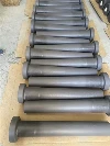
Installation Guide for NSiC Riser Tube: Step-by-Step Engineering Best Practices for Low Pressure Die Casting
Nitride-Bonded Silicon Carbide (NSiC riser tubes) provide foundry operators with an exceptional balance of mechanical rigidity, wear resistance, and high-temperature thermal conductivity. However, even the most durable refractory or structural ceramic conduit can fail prematurely if improperly handled during assembly. Studies across non-ferrous foundry cells show that over 60% of early-stage riser tube fractures result from improper mechanical clamping torque or inadequate preheating schedules rather than molten alloy erosion.
This authoritative technical guide outlines the standard operating procedures (SOP) for installing and commissioning an NSiC casting stalk tube in low pressure die casting (LPDC) machines and automated dosing furnaces. Adhering to these engineering steps ensures airtight pressure seals, prevents localized thermal shock, and maximizes production campaign uptime.
Phase 1: Pre-Installation Inspection & Tooling Preparation
Before introducing the tube into the furnace bay, complete a comprehensive receiving inspection to verify dimensional integrity and eliminate micro-fissures:
- Acoustic & Visual Crack Testing: Perform a ring test by lightly tapping the tube body with a wooden mallet. A clear, resonant pitch indicates sound structural integrity; a dull thud signals internal micro-cracks or delamination incurred during transport.
- Dimensional & Perpendicularity Checks: Inspect the seating flange face and outer diameter with dial calipers. Ensure the flange surface is flat within ±0.05 mm to guarantee uniform pressure distribution against the machine base plate.
- Furnace Collar Cleaning: Scrape off residual corundum buildup, molten splatter, and deteriorated fiber residue from the furnace lid adapter ring. Uneven contact surfaces create bending moments that snap ceramic collars under bolt preloads.
Phase 2: Gasket Selection & Flange Assembly Protocol
Direct metal-to-ceramic contact creates severe localized stress risers. A compliant, high-temperature thermal barrier must sit between the NSiC riser tube flange and the steel furnace lid plate.
| Installation Element | Recommended Material / Specification | Critical Engineering Function |
|---|---|---|
| Flange Cushion Gasket | High-purity bio-soluble ceramic fiber paper (2–3 mm thickness, uncompressed) | Absorbs thermal expansion differential between steel tooling and the NSiC body. |
| Thermal Insulating Ring | Precision-machined silicon nitride (Si₃N₄) or dense titanate backer ring | Arrests heat conduction toward mounting bolts; ensures planar clamping load distribution. |
| Fastener Configuration | Grade 8.8 or stainless steel hex bolts equipped with Belleville disc springs | Maintains constant clamping tension as furnace components expand during thermal cycles. |
| Flange Bolting Torque | 18 – 25 N·m (Cross-pattern torquing in 3 stages: 30%, 70%, 100%) | Prevents edge chipping and eliminates pneumatic bypass leakage during holding strokes. |
Critical Workshop Warning: Never use impact wrenches or standard pneumatic guns to tighten flange retaining bolts. Over-torquing on a single corner induces asymmetric shear strain, causing instantaneous collar detachment.
Phase 3: Recommended Preheating Curve
While Nitride-Bonded Silicon Carbide features superior resistance to thermal fatigue compared to standard oxide refractories, plunging a cold tube directly into $720^\circ\text{C}$ molten aluminum induces severe tensile hoop stress. Execute a gradual preheating ramp inside an external preheating station or above the open furnace holding bath:
- Stage 1 (Ambient to 200°C): Ramp temperature at 5°C–8°C/min. Hold at 200°C for 20 minutes to drive off surface humidity and absorbed moisture.
- Stage 2 (200°C to 450°C): Increase ramp rate to 10°C/min. Hold for 30 minutes to stabilize radial thermal gradients between the internal bore and outer wall.
- Stage 3 (Immersion Transition): Once the lower tip reaches a uniform dull red heat (~450°C–500°C), lower the stalk assembly smoothly into the molten aluminum holding bath at a continuous descent rate of approximately 50–100 mm/min.
Phase 4: Alignment & Die Interface Integration
In automated LPDC casting, the stalk tube orifice must align perfectly with the die sprue bushing or gating cup:
- Vertical Plumb Verification: Use a precision machinist level or laser guide to confirm that the stalk stands perpendicular ($90^\circ \pm 0.2^\circ$) to the furnace bath surface. Lateral deflection causes accelerated washing erosion on one side of the inner bore.
- Sprue Cup Clearance: Ensure an expansion clearance gap of 1.5–2.5 mm between the top nozzle tip of the NSiC tube and the bottom counterbore of the ceramic gating cup. Direct physical binding between the mold plate and stalk will transmit machine closing shock into the ceramic assembly.
Maintenance Tips to Extend NSiC Tube Working Lifespan
Proper daily operational hygiene preserves tube integrity and prevents premature replacement:
- Avoid Metal Scraping: Never use steel pry bars or cold chisels to clear aluminum dross from the tube mouth. Apply a thin coating of high-temperature boron nitride (BN) wash to the upper rim to promote self-releasing slag separation.
- Manage Furnace Level Variations: Avoid letting the molten alloy level drop below the lower third of the submerged tube. Rapid exposure to furnace atmosphere zones accelerates oxidation of the silicon nitride binder phase.
Reliable Foundry Ceramic Solutions from Shandong Anda Industrial
At Shandong Anda Industrial Co., Ltd., we manufacture high-performance structural refractories and technical ceramics designed for harsh non-ferrous foundry environments. Operating out of our modern 10,000㎡ manufacturing plant in Zibo, Shandong Province, and backed by 15 years of dedicated B2B international export experience, we supply durable NSiC riser tubes, reaction-bonded silicon nitride riser tubes, and complementary thermocouple protection sheaths to Tier-1 casting operations across the globe.
Every ceramic stalk is precision diamond-ground to tight geometric tolerances and subjected to thorough density and airtightness validation before dispatch. Our in-house engineering team provides complete technical support, from CAD drawing reviews to custom mounting adapter designs that seamlessly integrate with your existing LPDC machinery.
Need assistance optimizing your furnace riser tube assembly or reducing scrap rates? Contact our technical sales engineering team today for technical advice, installation drawings, and competitive volume pricing.